| HIFI-FORUM » English » DIY (Engl.) » DIY 300B DHT SE Amplifier Project | |
Gehe zu Seite: |vorherige| Erste Letzte
|
|
||||
DIY 300B DHT SE Amplifier Project+A -A |
||
| Autor |
| |
|
Gelscht
Gelöscht |
#51
erstellt: 19. Jan 2009, 16:26

|
|
|
Hi Let me guess the tubes. 6L6,EL34,6550,el37,6V6,KT66,807,-- --,45,300B,811, 211. Regards Rajiv |
||
|
aks07
Stammgast |
#52
erstellt: 20. Jan 2009, 06:32

|
|
|
Good and mostly correct calls ! Pentodes L to R 6CA7 EL34 6550 EL37 6L6G KT66 807 307A Triodes L to R 10Y 300B 811 845 Rajiv-ji wins this round by a slim margin for correctly IDing the EL37 which is a relatively rare bird. No wonder he is the resident classic gears guru in this forum. Bombaywalla-ji On the 1st tube we shall give you the benefit of doubt. Some 6550 were labelled like that. Usually they would be 7027 Waiting eagerly for your mods suggestions! [Beitrag von aks07 am 20. Jan 2009, 06:34 bearbeitet] |
||
|
|
||
|
viren
Stammgast |
#53
erstellt: 20. Jan 2009, 17:29

|
|
|
aks, Try and see if you can get by with a lower step-up on the interstage transformer. You are losing the advantage of the low plate resistance of the 5842 if you keep the step-up at 2.25. The reflected output impedance will go up by 5 (2.25 squared), from a value of 1.6k to 8k. Not a happy situation driving the 300B. Atleast the Lundahls offer you that flexibility. Rajiv, I've been following Jeff Medwin's crusade (because that's what it is!) on low resistance everything power supplies. What he says makes sense, if the power supply is stable. But try making a stable choke input supply with a choke of 0.22H! I gave Jeff the benefit of the doubt, got the chokes made, and tried it. The voltage ripple was enormous - no audio circuit will like that. By the way, the software PSUD modelled it perfectly well. No doubt, Jeff has made power supplies like it, but they require a tremendous amount of tweaking to work right. Just not practical! Viren |
||
|
aks07
Stammgast |
#54
erstellt: 21. Jan 2009, 12:49

|
|
|
At 1:2.25 ratio I measured the Lundahl LL1660 primary DCR at 273 ohms. I am thinking of a B+ of 180 volts and standing current of 20mA. That gives about 175vdc at plate. I am unable to post the equation and mathematic signs in the bulletin board. Maybe make a GIF file of the equation. But as per our choosen ratio of 1.2.225 we are getting - Mu = 43 - Rp of 5842WA = 1700 - IT primary R = 273 ohms, - Primary inductance = 33 henry (because for 1.2.25 ratio the primaries are connected in parallel this lowering the primary inductance of 130 by a factor of 4. At this ratio a max of output voltage of 250vrms is possible) Thus at 1Khz the amplification will be 95 and -3db will be at 9.83hz At your suggested 1.1.125 ratio we will certainly see an improvement on those numbers but I am worried if the stage will provide enough grunt to the 300B. In fact even before you correctly pointed out this, I was in a dilemma regarding this. I am also thinking of jacking up the supply to about 210 vdc and running the 5842 a little hotter if that helps. What is your valuable opinion on that? I think the best solution is to try both the ratios and judge which sound best ! |
||
|
viren
Stammgast |
#55
erstellt: 21. Jan 2009, 14:15

|
|
|
Hi aks, Yes, try both ratios and listen. We may be theorizing too much! Regards, Viren |
||
|
aks07
Stammgast |
#56
erstellt: 22. Jan 2009, 06:54

|
|
|
Great advice gratefully accepted ! Lets keep the slide rule away for the moment  I was thinking of independent power supply for the driver stage and output stage. I have read that in IT coupled designs its worthwhile to keep the rail separate for both sections? What is the consensus on that ? In this case our PSU cost will shoot up by at least 50%. Would it be worth that extra spending? Secondly, can DELTA wind Swinging Chokes ? |
||
|
Amp_Nut
Inventar |
#57
erstellt: 22. Jan 2009, 06:58

|
|
What are swinging chokes ? Thanks |
||
|
aks07
Stammgast |
#58
erstellt: 22. Jan 2009, 07:08

|
|
|
A swinging choke “swings” the henry as the drawn current decreases. High inductance when the current is low to better control the ripple. And low inductance when the current draw is high to prevent voltage drop outs. Sounds funky, isn’t it : ) |
||
|
Amp_Nut
Inventar |
#59
erstellt: 22. Jan 2009, 07:18

|
|
|
Hey, That is cool.  1. How is that done ? By driving the core close to saturation ? 2. What would be the ratio between the "High Current" and "Low Current ? " 2:1 ? Thanks for the info |
||
|
aks07
Stammgast |
#60
erstellt: 22. Jan 2009, 07:27

|
|
No idea how they are wound  I guess need to spend more time with the Radiotron Designers Handbook (4th edition)at the loo  |
||
|
sivat
Stammgast |
#61
erstellt: 22. Jan 2009, 10:13

|
|
Do you think it will be better if the PSU is designed to work...as LC(10uF)LC(100uF)C(0.1uF) I'm just throwing some values....but it might help to check using the tool from duncan amp. I'm not good at these numbers.. I believe it does help to tweak this B+ design.. Also, i noticed...AC is the solution for HT. Why not the design you have recommended earlier using a inductor from SMPS |
||
|
Manek
Inventar |
#62
erstellt: 25. Jan 2009, 11:15

|
|
|
Guys Plitron have been advocating toroidal transformers in the output stage as well and there are a few aes papers to that tune as well. What would you tube gurus say about toroidal as output transformers and would it suit our project here ? Manek |
||
|
aks07
Stammgast |
#63
erstellt: 30. Jan 2009, 14:03

|
|
|
Sorry for this hiatus due to an outstation tour. Sivat-ji That PSU is planned with whatever we have in hand. Shri Rajiv is sending a couple of BG caps. These have 100uf in two sections each. Thus 2 caps can be dived among L and R channels. The last cap is not to so critical and 15uf is sufficient for the decoupling. I might tweak the final PSU to hit the proposed op point. Piltron OPT Are they available in India? I believe they have an Indian winding business. |
||
|
quadtech
Ist häufiger hier |
#64
erstellt: 30. Jan 2009, 17:22

|
|
|
Salzer is the Indian associate of Piltron.  http://www.salzergroup.net/index.htm http://www.salzergroup.net/index.htm http://www.salzergroup.net/Transformers.htm http://www.salzergroup.net/Transformers.htmFound this contact posted by on diyaudio raymond (at) salzergroup.com Somewhat OT - can anyone suggest me good quality, locally available 100uf, 500V or similar cap? |
||
|
aks07
Stammgast |
#65
erstellt: 01. Feb 2009, 08:02

|
|
Thanks for that link. I will send them an email KELTRON makes reasonable quality elcos for PSU duty. They have 100uf/450volts (85deg). In my several years of use, none have exploded or gone bad even when exceeding the voltage rating. |
||
|
aks07
Stammgast |
#66
erstellt: 01. Feb 2009, 08:03

|
|
|
Decisions time now! Operating point: Our OPT is specified at 3000 ohm primary and 25 watts power rating. Max DC current 150mA. With that as a constant we have the following op points B+ 400. Grid -90vdc. Anode current 50mA. 2nd harmonic 21dB. Po 11 watts rms. B+ 350, Grid - -75vdc, Anode current 60mA. 2nd harmonics 26dB. Po 9 watts rms And several combinations in between. PSU: What is the verdict on split supplies for the output and driver stage? In our case when using IT coupling, is it a must to implement independent supply? In that case we are looking at a 50% cost escalation on PSU. I am sure both Viren-ji and Sivat-ji have grappled with this issue. Comments pls. |
||
|
viren
Stammgast |
#67
erstellt: 02. Feb 2009, 05:15

|
|
|
Hi aks, On the PSU, I've found that a LC section isolates the output stage from the input stage enough, to preclude separate supplies. Not worth the expense of using separate supplies. It does help to have separate transformers for the heater supply, though. Keeps noise in check. No idea of swinging chokes - Delta certainly hasn't made any. Viren |
||
|
aks07
Stammgast |
#68
erstellt: 02. Feb 2009, 06:51

|
|
I am sure Sivat-ji too has similar opinion. These are the specs for the PT TRANSFORMER 1 (MAIN HT) Primary 0-220-230 Secondary: Winding 1 440-370-CT-370-440 (400mA) Winding 2 5 Volts (3A) Winding 3 0 – 100 (50mA) Winding 4 3.15 – CT – 3.15 (2A) TRANSFORMER 2 (HEATER) Primary 0-220-230 Secondary Winding 1 3.15-2.5-CT-2.5-3.15 (2A) Winding 2 3.15-2.5-CT-2.5-3.15 (2A) Electrostatic winding between the primary and secondary for both the transformer? Viren-ji: May I request your good offices to find out if DELTA can custom wind the above two transformers? |
||
|
aks07
Stammgast |
#69
erstellt: 07. Feb 2009, 06:37

|
|
|
These are our penultimate schematics Amplifier:  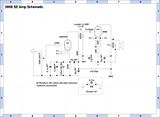 This design fulfills our basic aim of a simple plot involving just two active stages. The incoming signal is amplified to a voltage before the IT isolates it from the output stage. This also eliminates the need of a coupling condenser; fulfilling another of our design aim. The chosen ratio of 1:2.25 (more on that later) amplifies the signal to sufficient levels to drive the 300B. 300B is impedance matched via the output transformer to the speaker. We are using fixed bias scheme to set the quiescent current on the 300B. That allows us some flexibility on choosing our operating point and also saves the use of an electrolytic condenser right on the signal path. Another of our design goal met here. PSU:  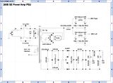 We have invested some heavy attention here. The PSU is the engine of any power amp. We want a PSU that is stable, provides sufficient headroom, has the lowest impendence/resonant frequency and good damping among other things It should provide a very clean power which is particularly important in a SE amp as the PSRR is worse than a Push Pull amp. And ofcource the PSU is bang in the signal path. We are using a tube/hybrid rectifier as pointed out by Shri Rajiv in an earlier post. Combines the best of the both world. Filament Supply:  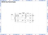 We are using an independent transformer for lighting up the 300B filament. Earlier the plan was to use AC heating. But DC seem to provides the best chance for a hum and noise free operation. We will use a pair of Common Mode choke that was retrieved from a computer UPS system. [Beitrag von aks07 am 07. Feb 2009, 06:42 bearbeitet] |
||
|
quadtech
Ist häufiger hier |
#70
erstellt: 07. Feb 2009, 12:00

|
|
|
Great work on the design and schematics. Looks like a real killer of an amp in the making. Isn't it better to add snubber caps across the semiconductor diodes to reduce switching noise? [Beitrag von quadtech am 07. Feb 2009, 12:03 bearbeitet] |
||
|
aks07
Stammgast |
#71
erstellt: 09. Feb 2009, 07:08

|
|
Thanks quadtech-ji. I think the HT section of the PSU needs some revision. The RC network ahead of the diodes will take care of the switching noise. Its better and more predictable solution than putting a cap across the diode. |
||
|
sivat
Stammgast |
#72
erstellt: 10. Feb 2009, 03:52

|
|
|
AKS-Ji, Actually i would like a separate PSU for input stage. But it might be an overkill and the cost difference can be put to good use else where for a more drastic improvement in overall sound quality. So finally, i do concur....but only because the the B+ in both stages are not very different (about 50v). Good design on the HT ... BTW which exact schottky are you planning to use. Most of the locally available ones seem to be dual in a configuration that forces us to parallel each diode on the bridge ? Regards Siva. |
||
|
Amp_Nut
Inventar |
#73
erstellt: 10. Feb 2009, 08:47

|
|
|
A lateral question, for my own knowledge... Which is better & why ...: A Bridge Rectified PSU or one with 2 diodes and a Centre Tap ? Thanks |
||
|
Amp_Nut
Inventar |
#74
erstellt: 10. Feb 2009, 09:16

|
|
|
sivat said :
I guess that the dual diodes are either Common Anode or Common Cathode. Either way, they can be used in a Bridge or Centre tapped Rectifier, without paralleling ... Or am I missing something ?  |
||
|
sivat
Stammgast |
#75
erstellt: 10. Feb 2009, 12:54

|
|
|
Amp_Nut, Center tap is not an option (Unless someone is willing to donate me a transformer) ;-) ...and i need a full wave bridge .. The other way is to use only one half of the dual diode... Regards Siva. |
||
|
Amp_Nut
Inventar |
#76
erstellt: 11. Feb 2009, 03:53

|
|
|
Hi Sivat, 1. My query for the CT vs Bridge PSU was for my academic interest only, not related to this project, as I had mentioned in my post. The voltage & current ratings of the Transformer will be different. Since Valave designers are usually GURUS  in Transformer design, I felt you guys were the best to answer this ... in Transformer design, I felt you guys were the best to answer this ...2. Sorry to persist, but a dual diode ( I assume these are either Common Anode or Common Cathode ? ) configuration Can be used in a Bridge rectifier without any 'wastage' of diodes, if you use 1 common cathode + 1 common anode pair. The common Cathode junction wil yield the + and the common Anode junction, the -ve. Ofcourse if a both configs ( common Anode & cathode ) are not available, you have a problem...  ... or shift to a Centre Tap PSU ... ... or shift to a Centre Tap PSU ... [Beitrag von Amp_Nut am 11. Feb 2009, 03:55 bearbeitet] |
||
|
sivat
Stammgast |
#77
erstellt: 11. Feb 2009, 04:01

|
|
You've got my problem. I just got some good single ones from digikey for use in my 845SE. They are more reliable... |
||
|
viren
Stammgast |
#78
erstellt: 11. Feb 2009, 04:51

|
|
|
Hi aks, The transformers have been ordered from Delta. Kudos to you for the way you are proceeding on this design! Viren |
||
|
aks07
Stammgast |
#79
erstellt: 11. Feb 2009, 08:47

|
|
|
Amp_Nut-ji All about full wave (that CT type), Bridge rectifiers and everything in between explained very nicely here.  All about birds and bees All about birds and beesNot that its required for an engineer like you, but nicely summarized nevertheless to brush up. Sivat-ji I will actually use Ultra Fast MUR860 diodes for the filament supply. These are in TO220 package. Saved from the days when OnSemi would send sample if you asked them nicely enough. For the grid voltage supply I will use OnSemi MUR180E (1A/1,000V) ultra fast diodes. I have couple of other types (including the dual config modules that you mentioned) and will be happy to send “samples” to you or any body else who needs them here. You have also rightly mentioned that the additional expense on separate supply rail for the driver section can be better utilized elsewhere. However, if you note our PT spec, you will see a tap at 380Volts on the main HT wiring. On a pinch we can use that to independently power the driver section if so desired at a later stage. |
||
|
aks07
Stammgast |
#80
erstellt: 11. Feb 2009, 09:01

|
|
|
Our main PSU is still posing some challenges cause we are working within a boundary with the following factor as a K -Use the 10H (90R) and 20H (130R) Chokes that I already have -Use the 100+100uf Black gate caps and find an igneous way to divide the section between the Left and Right channel. First the Chokes. While the 10H choke is quite ok, I am skeptical on the 20H choke. It has a pretty high DCR of 130R and I think that will put a serious dent on most of our design goals such as low impendence, resonance and such. Secondly, the BG pair is presenting a unique challenge. Ideally in a PSU the farads present themselves in an ascending order starting from the rectifier. But in our case we need to divide the BG between the channel, I am not liking the current configuration of 200uf > 100uf >15uf. It would have been a lot better in reverse order. One compromise would be 100u > 200uf > 15uf. While far from perfect, it look better than the first option. But in this case we shall be wasting a good 100uf section letting it idle. Heartbreaking. Below are some simulation with the 3 configuration The first option 200uf > 100uf > 15uf .   The Second option (wasting a section of one of the 100+100uf BG) 100uf > 200uf > 15uf   Third option (for academic purpose – we will not use it here; not using the full capacity of the 100+100uf BG’s) 15uf > 100uf > 100uf   Our interest is on the Green line in all the 3 options as that is the main HT voltage going into the 300B plates. BTW the excellent 100uf+100uf Blackgates arrived last week from Shri Rajiv. Not only the gift is precious, but he had taken obvious care in packing it so well in 3 layers. I appreciate that touch. I am sure that this amp will owe a lot to him. Thanks Rajiv-ji for your generous gift. Here is a pic of the BG’s  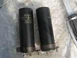 |
||
|
aks07
Stammgast |
#81
erstellt: 11. Feb 2009, 09:08

|
|
Viren-ji Thanks so much. That was fast ! Now you are setting the pace for this project to speed along Can you direct DELTA to provide full cover for the transformers? Both sides. Also, they seem to be using a EI core which is Length and Breadth is more. Can they use a smaller core and make up for the size in using a fatter stack? I think it will be about 3 inches. A squat and broad PT looks better and uses less footprint on the chassis. How much have they quoted for the trannies? And thanks also for the encouragement as usual. We need to discuss a little on the IT ratios. That has been bugging me for a while. |
||
|
aks07
Stammgast |
#82
erstellt: 12. Feb 2009, 03:30

|
|
|
Revisiting the driver section operating conditions - IT primary 273 ohms, - Supply rail 180v. Plate voltage at 175v - Grid Bias at 2v - Standing current at 20mA - Anode dissipation at 3.50 W - Mu at 43 - Rp of 5842WA at 1700ohm At these conditions the peak about 140vrms. Thus with the 5842 giving that kind of peak, Viren-ji’s suggested ratio of 1:1.25 will provide a gain of 43 and peak output swing of about 70vrms. The 300B at our load resistance of 3000R requires 61vrms for peak output. The big question: is that headroom of about 9vrms enough? If we can indeed get away with the ratio of 1:1.25, it should provide a boost to rated specs. Or is there a bigger picture here? We are fortunate that our Lundahl LL1660 offers a choice of primary and secondary ratios. I had started out this exercise with a ratio of 1:1.125 (as later suggested by Shri Viren as well), but noticed many gurus use a ratio of 1.2.25. I am hoping people like Shri Viren and Shri Sivat who use IT coupling can throw some light on this. |
||
|
viren
Stammgast |
#83
erstellt: 21. Feb 2009, 05:53

|
|
|
Hello aks, Delta has got back to say that bell caps on both sides of the filament transformer is possible. However, for the power transformer, in that core size, they have a cover only for one side. Can this transformer be mounted through a larger opening so that the open side faces down into the cabinet? If that's okay, we can proceed with the transformers. Viren |
||
|
aks07
Stammgast |
#84
erstellt: 22. Feb 2009, 11:23

|
|
Thanks Viren-ji The Santa Claus PT was also that type. There are two problems with that design. One, it occupies a bigger foot print. Second, its transmits a lot mechanical noise to the chassis. Can they increase the stack size? It will result in a fatter but squat transformer and perhaps they can uses some of their existing End Bell for that that. Or they can provide the existing cover for both sides. I will fabricate the feet’s so that PT remains upright. I think this is the best solution. PSU rethink Can you please ask DELTA if they can wind the following chokes 5H /250mA /DCR max 30R. 1 Qty 5H /120mA/DCR max 20R. 2 Qty I am having second thoughts on our original PSU design. Its is pretty good the way it is, but not the best that we can do. Two major drawbacks: 1.The awkward condenser build dictated by a desire to us the excellent 2 section 100+100uf Blackgates 2. The largish impedance of the PSU due to the higher DCR of the 20H chokes. If DELTA can wind the aforementioned chokes on reasonable money, they we can have a very good PSU. Thanks again ! |
||
| ||
|
|
||||
Gehe zu Seite: |vorherige| Erste Letzte
| Das könnte Dich auch interessieren: |
|
DIY. Simple Back Loaded Horn project with vintage BOLTON drivers aks07 am 12.10.2008 – Letzte Antwort am 24.12.2008 – 27 Beiträge |
|
DIY Projector sivat am 20.09.2006 – Letzte Antwort am 22.09.2006 – 3 Beiträge |
|
Santa Claus DIY Tube Amp screamgigi am 14.10.2006 – Letzte Antwort am 09.10.2007 – 237 Beiträge |
|
DIY Headphone amp Manek am 20.09.2006 – Letzte Antwort am 21.09.2006 – 25 Beiträge |
|
My DIY Interconnects ! Soundsgreat am 29.04.2009 – Letzte Antwort am 17.01.2010 – 10 Beiträge |
|
Working on ML-TL Transmissionline speaker project anilmn am 08.06.2010 – Letzte Antwort am 16.06.2010 – 5 Beiträge |
|
DIY 1X = Main Stream 4X bhagwan69 am 14.08.2007 – Letzte Antwort am 27.08.2007 – 94 Beiträge |
|
DIY Sub . sivat am 18.09.2008 – Letzte Antwort am 30.10.2008 – 24 Beiträge |
|
Eminence Lab 12 Subwoofer Project surrealistix am 14.11.2008 – Letzte Antwort am 27.11.2009 – 26 Beiträge |
|
My new DIY headphones Savyasaachi am 25.01.2009 – Letzte Antwort am 15.05.2011 – 6 Beiträge |
Anzeige
Produkte in diesem Thread

Aktuelle Aktion
Top 10 Threads der letzten 7 Tage

- Hotel Modus deaktivieren
- "diese anwendung wird jetzt neu gestartet um mehr speicherplatz verfügbar zu machen"
- Von HD+ zurück zu Standard-TV
- Remotekabel anschließen, aber wie und wo?
- Hisense verbindet sich nicht mehr mit dem WLAN
- Audiodeskription ausschalten (in ZDF App) 803er
- Umschalten von TV auf Radio
- Satellitenschüssel was und wie einstellen am TV
- Pro 7 und Sat 1 auf einmal weg.
- Markierung an Lautsprecherkabel - welche Norm?
Top 10 Threads der letzten 50 Tage

- Hotel Modus deaktivieren
- "diese anwendung wird jetzt neu gestartet um mehr speicherplatz verfügbar zu machen"
- Von HD+ zurück zu Standard-TV
- Remotekabel anschließen, aber wie und wo?
- Hisense verbindet sich nicht mehr mit dem WLAN
- Audiodeskription ausschalten (in ZDF App) 803er
- Umschalten von TV auf Radio
- Satellitenschüssel was und wie einstellen am TV
- Pro 7 und Sat 1 auf einmal weg.
- Markierung an Lautsprecherkabel - welche Norm?
Top 10 Suchanfragen

Forumsstatistik

- Registrierte Mitglieder928.520 ( Heute: 1 )
- Neuestes Mitgliedclimber74
- Gesamtzahl an Themen1.558.369
- Gesamtzahl an Beiträgen21.700.934
