| HIFI-FORUM » English » DIY (Engl.) » First tube amp.help a rookie? | |
|
|
||||
First tube amp.help a rookie?+A -A |
||
| Autor |
| |
|
Savyasaachi
Inventar |
#1
erstellt: 27. Feb 2009, 10:17

|
|
|
Alright, I just assembled my first tube headphone amplifier. I am trying to take some measurements.. How do you measure plate voltages, especially on the 12Au7 family of tubes..which is pin 1 and pin 6. What is the reference point to use when measuring these voltages? Is it just measured with respect to ground? |
||
|
viren
Stammgast |
#2
erstellt: 01. Mrz 2009, 05:00
|
|
|
Hi, Sorry, didn't get back to you earlier. Measure voltages with reference to ground. Use a clip lead to connect your DVM ground to circuit ground. Then use a probe connected to positive in the DVM to various circuit points. Change scale depending on the voltages you are measuring. This way you only have one hand close to high voltage points. Keep the other hand away! You lessen your chances of becoming the ground for your circuit! Regards, Viren |
||
|
|
||
|
Manek
Inventar |
#3
erstellt: 01. Mrz 2009, 14:46
|
|
|
Good advice sir Manek |
||
|
aks07
Stammgast |
#4
erstellt: 01. Mrz 2009, 19:47
|
|
|
Just adding to what Viren-ji has said, it would be helpful to familiarise yourself with HV precautions. Always wear footwear, remove wrist watch, use just one hand as you poke around. Be aware that capacitors retains their HV potential and would happy to discharge the load on you if touched accidentally. Dont fear HV but have a healthy respect for it to ensure your continued healthy existence. Once you have measured the voltages you would like to use that reading by employing Ohms Law which perhaps is the most important equation in designing or fault finding an electrical circuit. With the Ohm Law you can find voltage across resistors, current flowing through them, power ratings and several other stuff. I am sure you know about it; but just summarise the basic equation is V=IR, where V = voltage, I = current, in amps, and R = resistance, in ohms. Form that basic equation you can derive the equations for I (current) V (Voltage) R(Ohms) and P (watts) by rearranging the parameter as below. V = IxR R = V/I I = V/R P = VxI V = P/I I = P/V. P = I(sq)x R R = P/I (sq) I = sqr(P/R) P = V(sq) /R R = V(sq) /P V = sqr(PR) Its that simple ! Happy DIY. |
||
|
Savyasaachi
Inventar |
#5
erstellt: 01. Mrz 2009, 22:46
|
|
|
Thanks a lot for all the tips... My main problem is my inexperience with tubes...What does B+ mean?..what does it signify? Looking at a tube in a schematic makes no sesnse to me...How do I read a tube circuit? What is the importance of the heater? IN a triode, what are the 3 points and what do they signify as against say an NPN transistor. |
||
|
viren
Stammgast |
#6
erstellt: 02. Mrz 2009, 04:46
|
|
|
Hi, Probably the best you can do is get a basic text on this subject. Nothing like a good reference at hand. Look up: Beginner's Guide To Tube Audio Design - Bruce Rosenblit www.transcendentsound.comhttp://www.audioxpress.com/bksprods/BKSTUBDES.htmRegards, Viren |
||
|
quadtech
Ist häufiger hier |
#7
erstellt: 02. Mrz 2009, 08:04
|
|
|
Also, you can look on Amazon for Morgan Jones's books. |
||
|
Amp_Nut
Inventar |
#8
erstellt: 02. Mrz 2009, 08:31
|
|
|
Savyasaachi said :
Are you familiar with Transistors ? If yes, I could post some analogies between Transistors and Tubes...  |
||
|
sivat
Stammgast |
#9
erstellt: 02. Mrz 2009, 08:33
|
|
I recommend that you get someone experienced by your side to get started. These voltages can kill you.. |
||
|
Savyasaachi
Inventar |
#10
erstellt: 02. Mrz 2009, 08:36
|
|
|
yeah amp nut..am very familiar with transistors.. Thanks for the links Virenji..Will check it out.. The problem I have run in to now is that the amplifier is working..but there is a lot of distortion, constant noise . I resoldered the inputs and the pot to eliminate them as a problem. The other prototypers believe that my power supply could be a problem..I had accidentally switched polarities on one of the supply capacitors when I first turned it on... Waiting for additional powers supply section parts to arrive.. |
||
|
Savyasaachi
Inventar |
#11
erstellt: 02. Mrz 2009, 08:38
|
|
|
Thanks for the concern Sivatji.. I always wear sandals when doing work on the board. I do need to get some alligator clips though for one of the terminals on the multimeter instead of poking around on this really compact board.. |
||
|
Amp_Nut
Inventar |
#12
erstellt: 02. Mrz 2009, 09:10
|
|
|
Savyasaachi said
Sorry to see that no one has responded to your specific queries  For the Valave Pin out, there are several sites that explain this. One of them is : http://www.dogstar.dantimax.dk/tubestuf/pinout.htmBorrowing from that site : Looking at the tube (or socket) from the bottom, place the orienting indication (key or gap) at the top. The first pin to the right of this orienting indicator is Pin 1. The remaining pins are numbered in a clockwise direction from pin 1. An example is the common 9-pin miniature base (as 12AX7, 12AU7, etc.)  |
||
|
Savyasaachi
Inventar |
#13
erstellt: 02. Mrz 2009, 09:12
|
|
 My dinner table also masquerades as my workstation....   |
||
|
Amp_Nut
Inventar |
#14
erstellt: 02. Mrz 2009, 09:18
|
|
|
Time permitting ... I promise to post a small ( / )  'primer' on basiscs of tubes by today evening. 'primer' on basiscs of tubes by today evening.I do hope the Tube gurus will supplement the post(s). MUCH ahs been said about the cautions necessary while dealing with tubes... while this is .... IMHO VERY good advice, it should not nudge any DIY away from tubes. Infact, in many ways, Tubes are great fun for DIY... they dont die at the slightest provocation... unlike transistors.I will also post some 'Shocking Facts' first... even before the primer.... |
||
|
Amp_Nut
Inventar |
#15
erstellt: 02. Mrz 2009, 09:27
|
|
|
Savyasaachi
VERY simply and loosely put... B+ is the High Voltage from the power supply. This voltage is Usually fed to the Anode or 'Plate' of a Vaccuum Tube / Valve, through a series resistor (also called a load resistor). Some voltage is 'lost' / shows accross this load resistor. Hence, the B+ Voltage = The Volage drop accross the load resistor ( measure accross the 2 terminals of the resistor, NOT between Resistor and ground + The Anode or Plate Voltage ( Measured betwwen Power supply ground and the anode. |
||
|
Savyasaachi
Inventar |
#16
erstellt: 02. Mrz 2009, 09:31
|
|
|
Cool..thanks for that..I was wondering where this B+ was being used...My B+ test point reads 96 volts while pins 1 and 6 read 79 volts. Pins 1 and 6 are the plate pins. So If I am reading you right, the B+ is fed through a series resistor to arrive at the 79 volts at the plate pins... |
||
|
Amp_Nut
Inventar |
#17
erstellt: 02. Mrz 2009, 09:47
|
|
|
Purrrfect ! You catch on FAST !  |
||
|
Amp_Nut
Inventar |
#18
erstellt: 02. Mrz 2009, 11:15
|
|
|
SHOCKING FACTS ! We today come across references that indicate that a certain voltage is dangerous. These estimates of "Dangerous Voltage" vary widely. During my engineering studies, I got interested in the topic and had researched it a bit. I would like to share with you the facts (IMHO). VOLTAGES DO NOT KILL ! You will often read that a particular voltage say 1000 volts will kill a person. Not true. Voltage does not kill. In fact it is the current that flows through the body that kills. Voltage is similar to water pressure in a pipe of water and current is similar to the actual water flowing through the pipe. FATAL CURRENTS  1 mA (milli Ampere) = 1/1000 of an Ampere. AT LEAST 1 mA needs to flow through a human body before the body can sense any flow of current (i.e. provide the sensation of a mild shock). This ( 1mA) is called "Threshold Of Persecption." That is why when you touch your finger to an electric tester, and the neon glows, there is a series resistor inside the tester which limits the current to about 25% of 1 mA. Hence the neon glows, current flows through your body but you do not feel a shock ! THRESHOLD OF PAIN 10 mA is considered the "Threshold Of Pain" as the name suggests, it will cause a painful shock.  THRESHOLD OF DEATH THRESHOLD OF DEATH 30 mA is considered the Threshold Of Death. When 30 mA flows through the body (more specifically through the heart, it kills more than 90% of the victims. Incidentally, an electric chair ensures the passage of at least 100 mAs to ensure death ! The above current of statistical averages and not all persons react the same for the same current levels. ELECTRIC CURRENT & THE HEART Normal passage of electric current damages body tissues and can cause severe skin & muscle burns. However it rarely causes death UNLESS this current passes through the heart, which stops the heart from beating. That is why it is prudent to ensure that current does not flow from one hand to another hand or diagonally through one hand and a leg e.g. left hand down through the right leg because such a path will almost certainly include the heart. That is why your advice not to use both hands on a high voltage circuit and to keep your feet insulated by wearing rubber footwear. (Rubber is a MUCH MUCH better insulator than leather) BODY RESISTANCE Since by Ohms law the current passing through your body is equal to Voltage divide by Body Resistance, it is essential to keep the body resistance high so as not to get fatal shock. The body resistance varies with the person's health and also varies from individual to individual. More important, body resistance varies with how contact is made to the electrical point. A wet hand provides much better contact and lower contact resistance through the water, rather than a dry hand. That is why we have to be particularly carful in the bathroom, dealing with electricity when our hands and feet are wet. AC & DC CURRENT Much have been researched on the difference in shock from AC & DC currents. I had read a particularly interesting book by 2 Russian authors which documented several cases of shock were studied. They concluded that AC current (delivered from the wall outlet) was FAR MORE LETHAL than DC current. (used in valve audio). In fact their conclusions were extremely shocking viz : 1) No death was know to have occurred by a voltage less than 1000 volts DC !  ( Their conclusion, NOT mine ) ( Their conclusion, NOT mine )2) On the other hand, they found AC lethal, at even lower levels. In one case, death was recorded from a person's neck touching 12 volt AC wire used on a fence to detect if the fence had been broken into ! If you go by that, DIY Valve audio for all except high voltages used for the 845 tube ( and a select few others ) may shock you but will not kill you. I for 1 have not come across a single report on the internet of an audio DIYer being electrocuted…. Have You ?? DEADLY APPLIANCES Those technically included will know that every petrol car has spark plugs. Each spark plug receives electrical bursts of 10,000 volts DC or more ! Have you every heard of car mechanics being electrocuted ? I have not. This is despite the lack of education amongst most roadside mechanics. I remember, when in school, I tried to check if a spark plug was working , by holding an electric neon tester to the spark plug input. The shock was memorable… But did not kill. It does not kill because the electric delivered is about 2 to 3 mAs, particulars for the earlier, electro-mechanical distributors. The capacitor discharge ignition systems do pack a larger punch. The deadliest appliance in everyday use is supposed to be the microwave oven. It operates with more than 500 volts AC and a current of around 1 Amp at this high voltage. NEVER TINKER AROUND INSIDE A MICROWAVE OVEN. The next deadliest appliance is the photo flash. It generates 1,000 Volts DC and charges up capacitors which dump a huge current. I hope this rather long post provides scope for rational thinking and understanding what causes the shock and what does not. What is dangerous and what is not. DIY valve audio is great fun and not lethal. Please don’t get dissuaded. Sadly I see very little specific advice / feedback provided on this forum to specific queries on valve trouble shooting. Most of the replies begin and end with a caution note, which does little to persuade an enthusiasm for this hobby. [Beitrag von Amp_Nut am 02. Mrz 2009, 18:07 bearbeitet] |
||
|
Amp_Nut
Inventar |
#19
erstellt: 02. Mrz 2009, 11:26
|
|
The heater, literally heats the Cathode to a temperature high enough ( Several Hundred Degrees ) so that it starts emitting electrons. These electrons create the current flow in the 'Valve' or Vaccuum Tube.
Detailed explanation to follow in a Post, but for similarities : The Cathode in a Tube = Emitter in a transistor The Anode or 'plate' in a Tube = Collector in a transistor The Cathode actually Emits Electrons that are attracted by the high positive voltage on the 'Plate'. The electrons are Collected by the Anode or the plate. The 'Grid' or more correctly, the 'Control Grid' in a Tube = Base in a transistor [Beitrag von Amp_Nut am 02. Mrz 2009, 11:51 bearbeitet] |
||
|
Savyasaachi
Inventar |
#20
erstellt: 02. Mrz 2009, 11:33
|
|
|
That analogy makes things a lot more clear to understand for me understand a tube circuit now. I knew about the fact that current kills rather than voltage..but the bit about camera flashes and microwave oven were interesting.. And no, I haven't come across an audio DIYer being killed.. and hell no...its not going to deter me at all.. Am in the process of building another tube amplifier..and parts for yet another on hand and waiting for the boards to arrive. here is a pic of the case I have ready for one of the tube amps   |
||
|
Amp_Nut
Inventar |
#21
erstellt: 02. Mrz 2009, 12:15
|
|
While it would be helpful to have a circuit diagram or atleast some details of the Power supply ( Voltage, Capacitor Value & rating etc ... ) I would SPECULATE that there is no harm done. Electrolytic capacitors EXPLODE when they fail, and before that they begin to Bulge outwards... Any such signs of distress ? If yes, its not worth using.No physical signs ? Do an electrical test. Check the capacitor: 1. Remove 1 leg of the capacitor from the circuit. 2. Discharge it by shorting both of the capacitor's terminals. 3. With your Multimeter on the 20 K Ohms range, connect it across the capacitor. ( Dont touch your Hand on the 2 leads, as the body resistance will show up in parallel ) After holding the Ohm meter accross the Electrolyte cap, for about 10 to 20 seconds, the ohm meter should read ATLEAST 10K ohms. [Beitrag von Amp_Nut am 02. Mrz 2009, 17:46 bearbeitet] |
||
|
Amp_Nut
Inventar |
#22
erstellt: 02. Mrz 2009, 13:08
|
|
|
AUDIO 'VALVES' This post aims to provide a basic overview of Valve operation, with an emphasis on getting a 'feel' of how a Vacuum Tube Works, rather than the most accurate technical explanation. Associations will be made to audio applications, but can apply equally well to other applications. VALVE ??? Vacuum tubes are often called "Valves" because like air or water valves they control flow. They also permit flow only in 1 direction. The most basic type of vacuum tube is the DIODE. 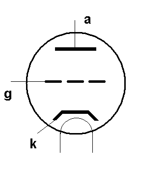 DIODE The Diode consists of a glass shell from which all air is removed i.e. a vacuum created. Inside the glass shell there is a cathode made of boron (?) This Cathode (k) emits electrons. To emit sufficiently large number of electrons, the Boron needs to be heated . An electrical heater or filament is wrapped around the cathode. ( Shown in the figure above as an inverted U thingi below the Cathode (If the filament directly and electrically touches the cathode, it is called "Directly Heated Cathode". If there is an electrical insulator between the filament & cathode, it is called an "Indirectly Heated Cathode".) Basic Physics Again: i. Electrons are negatively charged particles that are responsible for all electrical flow of current. ii. Also All negative charged particles are attracted by a positive charge/voltage. The electrons emitted by the cathode are attracted/pulled to the "Anode" (a) or 'Plate', situated a few millimeters away from the cathode. To attract a sufficient number of electrons (i.e. to establish an adequate electrical current flow) the anode (a) is maintained at a positive voltage. This positive voltage could be anything from about 24 volts DC to 1000 volts DC or more. If the distance between the Anode & Cathode is large and a larger current is required, a higher voltage needs to be established between the Cathode and Anode, to Pull the electrons from the Cathode (k) to the anode (a). Electrons (and therefore current) flow only from the Cathode to the Anode. Hence there is a single direction flow of electrons / current in a Diode. This property allows a Diode to be used in converting bi-directional or Alternating Current (AC) to a Direct Current (DC). The diode therefore forms the heart of a rectifier in a power supply in any audio device. TRIODE When the Diode is active (i.e. the Cathode heated and the Anode at a high positive voltage) electrons are happily streaming along from the Cathode to the Anode. THE GRID You can now insert a thin wire mesh (grid - g) in between the Cathode & Anode. If a negative voltage is applied to the wire mesh (g) it will repel the electrons and block some of them from getting pass this wire grid (g). (Remember that the electrons are negative charges & they are attracted to a positive voltage but repelled by a negative voltage. Similarly if the wire mesh (g) is made positive it will in fact assist in increasing the electron flow between the cathode & the anode since the electrons will first be attracted to the positive voltage on the wire mesh and then further pulled to the anode by the high positive voltage on the Anode. AMPLIFICATION If the wire mesh (g) is placed very close to the Cathode, even small voltages on the wire mesh will make significant changes to the flow of the electrons. BINGO ! We have AMPLIFICATION !... i.e. a small voltage on the wire mesh causes a large change in the flow of electrons between the Cathode & the Anode. Since the wire mesh controls the flow of electrons, it is called the "Control Grid". The vacuum tube consisting of the Cathode + Control Grid + Anode is called a Triode i.e. a device with 3 electrical connections. (The heater simply heats the Cathode to get electrons to boil over from the Cathode surface. Its role is therefore not directly part of the electrical amplification.) Savyasaachi had asked
HEATERS Earlier circuits used AC to feed the heater. No need to burden the rectifier. However, with the advent of cheap Solid State ( Not valve ) rectifiers, some used DC to feed the heater, and that reduced the 50Hz AC Hum on the audio signal, and the sound was better. Today, most use Regulated DC to feed Heaters, since Solid state diodes are cheap ( Rs 1 each, and you need 4 in a Bridge Rectifier … a 3 Terminal regulator will cost less than Rs 10 ). Expensive and cumbersome Valve rectifiers are used to create the B+ supply for the plate of the Audio tubes. .. much loved by audiophiles Whew ... This piece explains the DIODE & Triode. If someone is interested, I could write on the Tetrode ( 4 ) and the Pentode (5) to complete the intro to tubes. ( will be about 2 paras on each ) [Beitrag von Amp_Nut am 02. Mrz 2009, 13:27 bearbeitet] |
||
|
aks07
Stammgast |
#23
erstellt: 02. Mrz 2009, 14:31
|
|
|
Amp_Nut-ji What a riot you are !! You making it a reference thread. Prospective sticky material I have learnt at least 5 things that was just nominally aware of. Waiting eagerly for the time when you discuss biasing technics Keep going ! |
||
|
aks07
Stammgast |
#24
erstellt: 02. Mrz 2009, 14:47
|
|
If properly applied a 250v/30ma charge can kill you  I have known about a repair guy who died while installing a AHUJA tube amp. This was back in 70's and my uncle used tp have a shop renting out PA equipment. I thank God that in all my years of tube tinkering, I have never been zapped. I have always been very carful. I shudder to think what would happen. However, I have heard from oldtimers that the experince is quite nasty. I have had elcos exploding literally on my hands, tubes arching like thunder, transformers smoking and melting, resistors buring out brillint bright. They are all actually a lot less harmless than what it seems |
||
|
Amp_Nut
Inventar |
#25
erstellt: 02. Mrz 2009, 15:50
|
|
|
aks07 said :
Hi aks07, Thanks for the kind words. . Iam FLATTERED !
Sirji... I know when to stop drinking..... AND when to stop Yaking.. On that topic, YOU have to enlighten us... if the rest of the forum has even forgiven me for my post  (on just Diodes and triodes ! ) (on just Diodes and triodes ! )About the lethal zap from 230V, 30 mA ( I guess it HAS to be 30 mA to be lethal, unless he had a weak heart...) I presume : i. It was 230 VAC ( Not DC ) ii. Ohms law would indicated that his body resistance was just 8 K Ohms ( 240/30 ). He probably had VERY wet feet... and was Really unwell. since normal body resistance is closer to 200K even with a flu....But then again, if some one died with just 12 V AC ....  [Beitrag von Amp_Nut am 02. Mrz 2009, 15:55 bearbeitet] |
||
|
aks07
Stammgast |
#26
erstellt: 02. Mrz 2009, 17:14
|
|
Amp_Nut-ji I would be very very wary to meet you and while you giving a demo of your tube gear! You have some very lethal knowlegde ! Sorry for OT. Speaking of tubes, bonavolta tube pages are excellent primer. |
||
|
Arj
Inventar |
#27
erstellt: 03. Mrz 2009, 05:35
|
|
Human body resistance varies . in the end R(body) = R(Contact) + R(skin) + R(internal) R(Contact)is the most important and varies depending on the kind of contact and moisture content on the surface of the skin. for it to be really deadly the conductor should pierce the skin R(internal) is pretty low due to the amount of Water in our body..between 200-800 ohms ! the fat and bones are insulators R(Skin) is the max resistance area..can be between 1K to 1M ohms depending on the status of the moisture in the skin .dry skin is the safest. Also if you are using your left hand then keep your left leg on the ground and your right leg ideally out of contact from the ground and vice versa..so even if you do have cuyrrent passing thru it will not go via your vital organs (I meant heart..)So if you want to save yourself..have lot of Ghee and keep your skin dry amd stand on one leg  |
||
|
Amp_Nut
Inventar |
#28
erstellt: 03. Mrz 2009, 05:48
|
|
|
Arj said :
Interesting info, Arj. Thanks I did not know it was THAT low... ! Ties in well with a lethal shock at 230VAC... IF the conductor pierces 2 hands simultaneously.. |
||
|
Savyasaachi
Inventar |
#29
erstellt: 05. Mrz 2009, 07:58
|
|
|
It lives ..by god it lives.. Had a real hard time replacing 2 transistors...Almost got one of the pads off  Replacing the MPSA42s (the high voltage amplifiers in the power supply) did the trick...the amp is super quiet..no noise at all with the volume up all the way. Also got most of the case work done. Just need to get a couple of panel mount toggle switches (for the heater and the turn on/off), drill holes for them, a hole for tube replacement and a hole for the LED... I'm almost there.. Man does it sound sweet..driving my Fostex T50RP like a champ..brilliant! Thanks to Alex Cavalli for such a great design...me going back to spend about half an hour listening to this beauty before I need to get back to other work..My first tube amp ever, DIY or otherwise!! |
||
|
Amp_Nut
Inventar |
#30
erstellt: 05. Mrz 2009, 10:49
|
|
|
|
||
|
Savyasaachi
Inventar |
#31
erstellt: 06. Mrz 2009, 09:40
|
|
|
indeed amp_nutji.. also I finally got myself a Fluke multimeter...bouhgt one used for 70$..a great deal IMHO. Its an 87 series 3..originally sold for like 400$ new and still sells used from 130-180 used on ebay... very very happpy.. |
||
|
Savyasaachi
Inventar |
#32
erstellt: 08. Mrz 2009, 03:02
|
|
|
A few pics of the amp cased up..need to drill the hole on the top plate for the tube..    |
||
|
aks07
Stammgast |
#33
erstellt: 08. Mrz 2009, 09:26
|
|
|
Savyasaachi-ji Doode..i envy. You got a built a lovely tube amp ..got a Scott Nixon DAC ..a hottie GF and now even a Fluke multimeter! What more could a guy desire ? I am sure most of old geezers here ( such as Amp_Nut-ji, ) too share this envious feeling.Enjoy your days ! |
||
|
Manek
Inventar |
#34
erstellt: 08. Mrz 2009, 10:36
|
|
|
Aks-ji Don't feel too envious cause a few hotties do prefer old geezers :-) all you need is a bit of moolah....hee hee... Fluke meters are the stuff to own isn't it ? Nice pickings sachi but I'm sure the best is yet to come. Manek |
||
|
Savyasaachi
Inventar |
#35
erstellt: 20. Mrz 2009, 09:53
|
|
|
Final pics of my prototype CTH build.. Isn't it puurty   http://img8.imageshack.us/img8/1619/img1488r.jpg http://img8.imageshack.us/img8/1619/img1488r.jpg  http://img13.imageshack.us/img13/563/img1533h.jpg http://img13.imageshack.us/img13/563/img1533h.jpg http://img13.imageshack.us/img13/8905/img1534f.jpg http://img13.imageshack.us/img13/8905/img1534f.jpg  The CA is my way of paying tribute to the design house that created the amp..Cavalli Audio. CTH in Star Wars font for the amp..serving dual purpose.. Nice convection air currents between the two sets of holes to cool her down so she doesn't burn herself from her hot sexy self. |
||
|
Savyasaachi
Inventar |
#36
erstellt: 23. Mrz 2009, 11:03
|
|
|
I recently had a micro meet at my place..mainly to test out amps and sources Results from the micro meet at my place...I will try to put it in as few words as possible.. CTH(w 12BH7A Gold Aero) -> AKG K701 Good *Very nice air.wide soundstage, excellent highs * very good mids..would like the vocals to be a bit more forward Bad *Bass is loose *Seems like it can't get the bass out of the K701s as easily.. *just a wee bit bright for my tastes Don's original Stacker -> K701 Good Faster and tighter bass.. sound staging is brilliant..the drivers seem to disappear The brightness that was there in the CTH was no longer there. Very nice detailing but some passages sounded a tad muddled..but nothing too great Fantastic mids..perfect and on the spot CK2III- > K701 Good *Decent bass.. *drives the K701 adequately *Good mids..not as musical but more forward than the CTH Bad * Not musical at all..easily noticeable going from the other two amps to the CK2III. *Sound stage is smaller than the other two *Rolled off highs..lacks detail, lacks the air that the other two amps have in spades *Bass was slightly loose but generally ok Starving Student (SS)->K701 Good *Decent mids..but a bit forward sounding. *Decent Bass..feels like the amp has a lot of juice *CTH seems to have looser bass Bad * Bass lacks control *Not as detailed in the highs as the CTH...lacks the air *better channel separation on the CTH *Sounds muddled at places compared to the CTH, lacks details SS With Fostex T50Rps (heavily damped) -> Muddiness in the sound is not that apparent..the SS definitely feels like it has more power.(wonder if changing a few resistors on the CTH would help address this. Bass sounds slightly hollow CTH with Fostex T50RP -> Better air, details and bass than the SS. CTH with Yamaha HP2 -> It seems to driev my orthos wuite well...sounds really good with my HP2. I love this combo.. ____________________________________________ We gave the CK2III only one listen before we relegated it to one corner disconnected and lonesome. It is already sold and heading off to its new owner come monday. Swapping out the 12BH7A with an RCA 5963 improved the bass wuite bit..it got tighter..seemed to drive the K701 ok. However, the highs seemed to roll off earlier with the 5963. Things that I noticed were, the E12 took longer to trip when we plugged in the K701 and the Yamaha Yh-100s..normally it took half that time with other headphones. I had plans of selling the Starving student..but I am not so sure anymore. I am also not so sure about building another CTH. Especially considering I want to build few other amps. A word about the stacker...awesome!!!.it just makes it seem like a piece of cake for it..seamless and smooth in its presentation..devoid of any shortcomings..delivering music like it should be...fun!!!     |
||
| ||

|
|
||||
| Das könnte Dich auch interessieren: |
|
Bought my first tubes.now need an amp to put them in Savyasaachi am 09.02.2009 – Letzte Antwort am 11.02.2009 – 5 Beiträge |
|
Santa Claus DIY Tube Amp screamgigi am 14.10.2006 – Letzte Antwort am 09.10.2007 – 237 Beiträge |
|
More tube projects on the starting block Savyasaachi am 24.03.2009 – Letzte Antwort am 11.03.2010 – 31 Beiträge |
|
My first pair of DIy interconneccts. Savyasaachi am 16.08.2007 – Letzte Antwort am 17.08.2007 – 7 Beiträge |
|
My second DIY tube amp .The starving student Millet Hybrid Savyasaachi am 11.03.2009 – Letzte Antwort am 18.03.2009 – 13 Beiträge |
|
DIY Headphone amp Manek am 20.09.2006 – Letzte Antwort am 21.09.2006 – 25 Beiträge |
|
Sachiko speakers done quadtech am 11.06.2009 – Letzte Antwort am 21.05.2017 – 9 Beiträge |
|
DIY. Simple Back Loaded Horn project with vintage BOLTON drivers aks07 am 12.10.2008 – Letzte Antwort am 24.12.2008 – 27 Beiträge |
|
Coupling and bypass Capacitors? Savyasaachi am 04.06.2010 – Letzte Antwort am 08.03.2011 – 10 Beiträge |
|
building a sub SUNILYO am 28.09.2006 – Letzte Antwort am 04.10.2006 – 7 Beiträge |
Anzeige
Produkte in diesem Thread


Aktuelle Aktion


Partner


Top 10 Threads der letzten 7 Tage
- Hotel Modus deaktivieren
- "diese anwendung wird jetzt neu gestartet um mehr speicherplatz verfügbar zu machen"
- Von HD+ zurück zu Standard-TV
- Remotekabel anschließen, aber wie und wo?
- Hisense verbindet sich nicht mehr mit dem WLAN
- Audiodeskription ausschalten (in ZDF App) 803er
- Umschalten von TV auf Radio
- Satellitenschüssel was und wie einstellen am TV
- Pro 7 und Sat 1 auf einmal weg.
- Markierung an Lautsprecherkabel - welche Norm?
Top 10 Threads der letzten 50 Tage
- Hotel Modus deaktivieren
- "diese anwendung wird jetzt neu gestartet um mehr speicherplatz verfügbar zu machen"
- Von HD+ zurück zu Standard-TV
- Remotekabel anschließen, aber wie und wo?
- Hisense verbindet sich nicht mehr mit dem WLAN
- Audiodeskription ausschalten (in ZDF App) 803er
- Umschalten von TV auf Radio
- Satellitenschüssel was und wie einstellen am TV
- Pro 7 und Sat 1 auf einmal weg.
- Markierung an Lautsprecherkabel - welche Norm?
Top 10 Suchanfragen
Forumsstatistik
- Registrierte Mitglieder928.520 ( Heute: 1 )
- Neuestes MitgliedDzxlasJem
- Gesamtzahl an Themen1.558.388
- Gesamtzahl an Beiträgen21.701.251
